1. a) Describe how the focal length of a convex mirror can be measured using a convex lens of a known focal length.
ii) The plane mirror, P, figure 1 is adjusted to a position 20cm from the optical pin, the image of the pin in P coincides with its image in M.
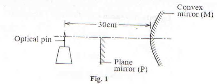
Calculate the focal length of the convex mirror.
b) A pin is clamped horizontally above a concave mirror with its tip along the principal axis. When the pin is adjusted, it coincides with its image at a distance R from the mirror. When a small amount of liquid of refractive index, n, is put in the mirror, the pin again concides with its image at a distance R from the mirror. Show that the refractive index, n, is given by

c) i) Explain the term eye-ring as applied to a telescope?
ii) Draw a ray diagram to show the formation of a final image in a Galilean telescope in normal adjustment.
iii) Explain two advantages and one disadvantage of the telescope in (c) (ii).
2a) What is meant by the following as applied to waves?
i) Resonance
ii) Frequency
b) Explain with the aid of suitable diagrams, the terms fundamental note and overnote as applied to vibrating air in a closed pipe.
c) Describe how you would determine the speed of sound in air using a resonance tube and several tuning forks.
d) i) Explain the formation of beats
ii) Derive the expression for the beat frequency.
e) Two observers A and B are provided with sources of sound of frequency 750Hz. If A remains stationary while B moves away at a velocity of 2.0ms-1 find the number of beats heard per second by A.
(Velocity of sound in air = 330ms-1)
3. a) i) When does light pass through a prism symmetrically?
ii) Find the angle of incidence, i, an equilateral prism of refractive index 1.5 placed in air, when light passes through it symmetrically.
iii) Describe what happens to the deviation of light passing through the prism in (a) (ii) when the angle of incidence is increased from a value less than i.
b) Describe how the refracting angle of a prism can be determined using optical pins.
c) i) Draw a sketch ray diagram, showing formation of the image of a finite size real object by a concave lens.
ii) A concave lens of focal length 15.0cm is arranged coaxially with a concave mirror of focal length 10.0cm, distance of 4.0cm apart. An object is placed 20.0cm in front of the lens, on the side remote from the mirror.
Find the distance of the final image from the lens.
d) With the aid of a sketch ray diagram explain spherical aberration in concave lenses, and state how it is minimized.
4. a) What is meant by diffraction?
b) Explain using Huygen’s principle, the diffraction pattern produced by a single slit.
c) Light of wavelength 5.0 x 10⁻⁷m falls on a grating with 600 lines per mm. Determine the highest order of diffraction that can be observed.
d) i) Explain what is meant by the plane of polarization of light.
ii) A liquid of refractive index 1.3 is used to produce polarized light by reflection. Calculate the angle of incidence of light on the liquid surface.
e) i) Describe how the polarized light can be produced by reflection.
ii) State two uses of polarized light.
5 a) i) What is the difference between a motor and a dynamo?
ii) Describe with the aid of a labeled diagram the structure and mode of operation of a d.c generator.
iii) Describe briefly the factors that determine the peak value of the induced e.m.f.
iv) How can a d.c generator be converted into an a.c generator?
b) Figure 2 shows two wires AB and CD of length 5.0cm each carrying a current of 10.0A in the direction shown. A long conductor carrying a current of 15A is placed parallel to the wire CD, 2.0cm below it
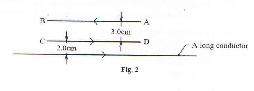
i) Calculate the net force on the long wire.
ii) Sketch the magnetic field pattern between the long wire and the wire CD after removing wire AB. Use the field pattern to define a neutral point.
6. a) What is meant by the following as applied to the earth’s magnetic field?
i) Magnetic meridian
ii) Magnetic variation.
b) Describe the structure and mode of action of the deflection magnetometer.
c) A circular coil of four turns and diameter 11cm has its plane vertical and parallel to the magnetic meridian of the earth. Determine the resultant magnetic flux density at the centre of the coil when a current of 0.35A flows in it.
(Take the horizontal component of the earth’s magnetic flux density to be 1.6 x 10⁻⁵ T).
d) i) Define self- induction and mutual induction.
ii) Give the causes of power loss in an a.c transformer and state how each can be minimized.
iii) Explain why the current in the primary coil of a transformer increases when the secondary is connected to a load.
7. a) Define root mean square (rms) value of an alternating voltage.
b) A resistor of resistance 100Ω is connected across an alternating voltage V = 20 sin 120ᴨt
i) Find the frequency of the alternating voltage.
ii) Calculate the mean power dissipated in the resistor.
c) i) Show that when an inductor is connected to an a.c supply voltage of V = V0 sin 2ᴨft, the resulting current lags the voltage by 900.
ii) Sketch on the same axes the variation with time of the voltage and current if a capacitor is connected to the voltage supply in (c) (i).
d) i) Describe how a thermocouple meter works.
ii) Explain any precautionary measure taken in the design of the thermocouple meter.
e) A capacitor of capacitance 60μF is connected to an a.c voltage supply if frequency 40Hz. An a.c ammeter connected in series with the capacitor reads 2.2A. Find the p.d across the capacitor.
8. a) i) Define electrical resistivity
ii) Explain how length and temperature of a conductor affect its resistance.
iii) Figure 3 show the current –voltage graphs for a metallic wire at two different temperatures T1 and T2.
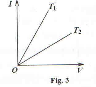
State which of the two temperatures is greater and explain your answer.
b) i) Derive the balance condition when using a metre bridge to measure resistance.
ii) State two precautions taken to achieve an accurate measurement.
c) Figure 4 shows two resistors P and Q of resistance 5Ω and 2 Ω respectively connected in the two gaps of the meter bridge.
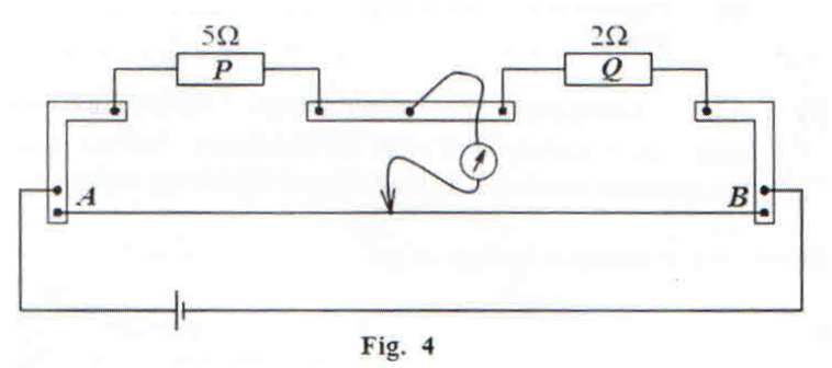
A resistance X of cross –sectional area 1 mm2 is connected across P so that the balance point is 66.7cm from A. If the resistivity of wire X is1.0 x 10-5 Ωm and the resistance wire AB of the meter bridge is 100cm long, calculate the length of X.
d) Explain how electrons attain a steady drift velocity when current flows through a conductor.
9a) i) Explain an equipotential surface.
ii) Give an example of an equipotential surface.
b) i) State Coulomb’s law.
ii) With the aid of a sketch diagram, explain the variation of electric potential with distance from the centre of a charged metal sphere.
iii) Two metal plates A and B, 30cm apart are connected to a 5kV d.c supply as shown in figure 5.
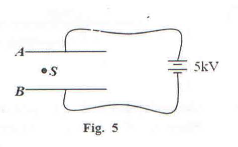
When a small charged sphere, S, of mass 9.0 x 10⁻³ kg is placed between the plates, it remains stationary. Indicate the forces acting on the sphere and determine the magnitude of the charge on the sphere.
c) i) Define electric field intensity.
ii) With the aid of a diagram, explain electrostatic shielding.
d) Explain briefly why a neutral metal body is attracted to a charged body when brought near it.
10. a) i) What is meant by capacitance of a capacitor?
ii) A parallel plate capacitor is connected across a battery and charged fully. When a dielectric material is now inserted between its plates, the amount of charge stored in the capacitor changes. Explain the change
iii) Describe an experiment to determine the relative permittivity of a dielectric.
b) A network of capacitors of capacitances 40μF, 50μF, and 70μ F is connected to a battery of 9V as shown in figure 6
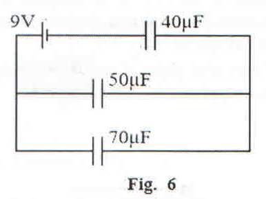
Calculate
i) charge stored in the 50 μF capacitor.
ii) energy storedin the 40 μF capacitor.
c) Explain corona discharge.
END